Electrical treatments
C.E.S
Electronic frequecny use in the treatment of diseases have been used.
A delta wave, also known as delta rhythm, is the
normal brainwave in the encephalogram of a person in deep, dreamless sleep,
occurring with high voltage and low frequency (1 to 4 Hz). If you plan to design
and develop your own brain tickler (or similar) system as an academic, amateur,
or professional electronics project, this easy-to-build circuit — centered
around an inexpensive CMOS chip — is for you. This battery-powered minuscule
circuit can be exploited as an adaptable delta wave generator to help someone
suffering from chronic insomnia (chronic sleeplessness).
Delta Waves & Cranial Electrotherapy Stimulation
Delta waves are the slowest recorded brain waves
in human beings. They are found most often in infants and young children. As we
age, we tend to produce fewer delta waves, even during deep sleep. They are
associated with the deepest levels of relaxation and restorative, healing sleep.
They have also been found to be involved in unconscious bodily functions, such
as regulating heartbeat and digestion. Adequate production of delta waves helps
us to feel completely rejuvenated after we wake up from a good night’s sleep. If
there is abnormal delta activity, an individual may experience learning
disabilities or have difficulty maintaining conscious awareness.
Cranial electrotherapy stimulation (CES) is a
process which utilizes extremely small levels of electrical stimulation across
the head for therapeutic treatment of anxiety, depression, insomnia, and chronic
pain. CES is a relatively simple treatment; it employs a small, battery-powered
device that is similar in size and appearance to transcutaneous electrical nerve
stimulators (TENS) devices commonly used in physical therapy for pain relief but
produces very different waveforms at a much lower current level. The CES device
sends pulses of very low amperage (less than 1 mA) electricity through thin
wires attached to electrodes clipped to the earlobes or stuck to the skin over
the bony prominences just to the front of or behind each ear. The frequency of
the electrical pulses can be adjusted — usually from 0.5 Hz to 100 Hz —
depending on the desired treatment effect.
Cranial electrotherapy stimulation device.
Simple DIY CES Device
This is an introductory/demo design of a variable
frequency CES device that is safer than many other ideas found on the internet.
This device, configured as a delta wave generator to help people suffering from
chronic insomnia, outputs a “clean” bipolar symmetrical square wave of a
frequency a little below 1 Hz.
Above are square waves of a zapper
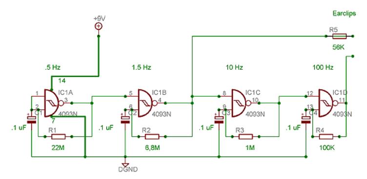
Circuit diagram of the variable frequency cranial electrotherapy stimulation
device.
As can be seen from the circuit diagram, the
heart of the device is a “cheap” CD4069 (IC1) configured as a simple RC feedback
oscillator with the help of its first two gates (IC1A-IC1B). Components R1, R2,
R3, and C3 determine the frequency. The 4.7-M multi-turn preset potentiometer
(RP1) can be used to fine-tune this frequency to some extent. Similarly, the 10K
multi-turn preset potentiometer (RP2) controls the intensity of the output
pulses available through the proves P1 and P2. The red lamp (LED1) simply works
as a device status (run/stop) indicator. The whole device can be powered from a
6-V (1.5-V x 4) battery supply.
Three types of biomedical electrodes useful for this design: earclips, needle
probes, cleave pads.
Did You Know?
CES has been used in numerous countries around
the world for more than 40 years as an effective non-drug therapy (acupuncture
without needles) to balance neurotransmitters. This design can be used to
deliver an adjustable tingle to your earlobes that balances your nervous system
so that you feel at ease and capable of working, playing, meditating, focusing,
or sleeping whenever and wherever you like.
Notes & Warnings
• A true RMS digital ac voltmeter is necessary to adjust the output intensity
(output voltage). Similarly, a precise digital frequency counter is essential
for calibration of the output frequency. However, with a CRO/DSO, it is possible
to carry out these two tasks efficiently.
• In
my prototype, a 100-uF/25-V capacitor (C2) is connected across the 100-n
capacitor (C1). Later, it’s removed and, thus, you can’t see a capacitor
labelled as C2 in the presented circuit diagram.
• The 33-n capacitor (C4) helps prevent ringing and unwanted noise injection on
the outputted square waves. Another good value for this capacitor is 39 n.
• Although I have successfully built and tested this design, performance is not
warranted. I hold no responsibility; hence, use the device at your own risk.
Those who are epileptic, pregnant, or have a pacemaker (or any other bioelectric
device) should consult their doctor before use!
Read more about OUR links below
Energy drinks
Say No TO FORCED vaccination
LeRoy Franco
Asofoendtida
Peppers
Bitter Gourd and ITP
Longevity
DHEA
Curry Powder
Water chestnut
Beet Root anti cancer
Green tea and cancer risk
Dementia and exercise
Exercise and weight loss
Sleep and stay fit
avoid episiotomomy
FLU SHOT NO
Hyperacusis
Spine
Narcolepsy
Eclampsia & autoimmune
Multiple Medications
Healthy Oils
Sulfur baths
Caly baths
Steaming Sand Baths
Soccer Player & Arthritis
Body Building supplements
Athlete gets GBS
Chromium in Health
Colostrum